TerpyTyrone
LED Recruiter
Uh oh. Its just on the pot . I got the second druver with the pot built,inFor electrical it should be rosin core solder. Plumbing uses acid core solder.
Uh oh. Its just on the pot . I got the second druver with the pot built,inFor electrical it should be rosin core solder. Plumbing uses acid core solder.
It might just cause some resistance in the connectionUh oh. Its just on the pot . I got the second druver with the pot built,in
I was getting 70 ohm from the first one so I changed it to the 130 ohm pot. Maybe I should bring my tester over there and see how many watts it's actually pulling.It might just cause some resistance in the connection
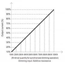
Good info hereMy phone is glitching and making it hard to look at the pics, but if your POT is just used for an aftermarket additive resistance method of dimming on a "b" style driver, then you'll be fine. Most use @ least a 110kΩ POT for the dimmers so you get the full range. If theres no current flowing through the dimmer leads the driver will be at max output, so using a 110kΩ POT just ensures you can achieve the max 100kΩ needed for full blast.
View attachment 5852
If you want to determine resistance, you can switch to the resistance portion of the multimeter and test Ω without any power being run through the dimmer. Just connect the "+" multimeter probe to one dimmer terminal and the "-" probe to the other dimmer terminal (no power hooked up to dimmer). Select 200kΩ on your multimeter and you should get a reading.
EDIT:
Voltage is measured in parallel. Current is measured in series. Volts × Amps = Watts.
So if you were trying to obtain wattage you'd have to measure voltage in parallel while its on, then power down, disconnect the cct or make a break in the loop, insert multimeter in series with the loop, then turn the multimeter dial to the "current" portion, then power back up and measure current. Then multiply the voltage by the amperage and you'll have wattage.
Your the man!My phone is glitching and making it hard to look at the pics, but if your POT is just used for an aftermarket additive resistance method of dimming on a "b" style driver, then you'll be fine. Most use @ least a 110kΩ POT for the dimmers so you get the full range. If theres no current flowing through the dimmer leads the driver will be at max output, so using a 110kΩ POT just ensures you can achieve the max 100kΩ needed for full blast.
View attachment 5852
If you want to determine resistance, you can switch to the resistance portion of the multimeter and test Ω without any power being run through the dimmer. Just connect the "+" multimeter probe to one dimmer terminal and the "-" probe to the other dimmer terminal (no power hooked up to dimmer). Select 200k on your multimeter and you should get a reading.
I like the blend. If you can extend the SPD width a bit by adding farther red or farther blue I think you'd notice even better results. But what do i know lol I have yet to add any far red! I need to get on it!Your the man!
I love the graphics in ur threads. Very informative. What do u think of my spectrum.
4 qb 132 3000k, 4 qb132 4000k.
I will interchange them so each light will have 2 of each on it to give each plant in the 4x4 equal spectrum.
I really wanted the 3500k but hlg didnt restock em,in time,for me, so I pulled the trigger and got,the 4k.
Just in time too. The twmps in the NE are rising and I had to get the hps outta there.
When I make another move in the tent, I may just take the drivers right out of the tent. The 20/2 thermostat wire I got should be able to go the 8-10' span without a voltage drop, no?
I didnt have time in your thread about spectrums to comment, but in that paper the guy mentions that by adding red it doesn't speed up the flowering rate/time but it does add to the way the cannabis metabolized the nutrients?

It would probably be 91 with a hps. What is the pic of the ant that is almost finished , it looks pretty tastyWith the drivers on top of the lights , in the tent, the temp,was up,to,81 today. On a relatively mild spring day. By buying these LED boards I was hoping to be able to run damn near ambient temp outside the tent.
You can get the lights to run cooler by increasing the area over which the power is applied (ie, same wattage, but more chips or more boards, = cooler temps). Although you can't make the driver run cooler, so if you keep the drivers outside the tent you'll manage inside ambient easier.With the drivers on top of the lights , in the tent, the temp,was up,to,81 today. On a relatively mild spring day. By buying these LED boards I was hoping to be able to run damn near ambient temp outside the tent.
SEEDSMAN amnesia auto.It would probably be 91 with a hps. What is the pic of the ant that is almost finished , it looks pretty tasty
How do u make these cool diagrams!! U missed your calling brother!Also, be safe when measuring the current.
Set your space up first. Power disconnected. Then, after power is disconnected, hook up your multimeter to the cct so it doesn't move around even if bumped lightly, its best if you can plug the 2 ends of the open cct directly into the multimeter, or use alligator clamps. Then after you have your multimeter in series rotate your multimeter dial to the 10A position (make sure the multimeter probe is in the 10A hole, or the end of the cct goes in the 10A hole), and then finally power your cct, or plug the driver in.
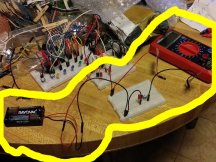
Here's a quick example of measuring current.
3v battery pack "+" goes through multimeter, then through 1kΩ POT, then through red LED, and then back to battery pack "-." You can see here where I've broken the cct or opened the loop, and the 2 leads lay dangling to the left of multimeter. They have duct tape on them so when I insert them into the multimeter holes they make a solid connection and stay in place. With low power its not such a big deal but if this were a 600h(?) then ya it matters. Just safer.
View attachment 5864
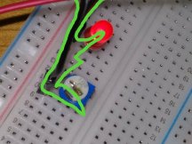
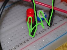
Close up of the path of the current, from "+" of battery through POT, through LED, to "-"
View attachment 5865
View attachment 5866
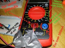
I only measured the current of a small battery pack, so my max current selection on the multimeter was 200mA, if I were measuring over 200mA+ then I'd have to switch the hole where the red positive wire is in this pic below to the 10A hole on the far right instead of in the middle, and then Id rotate the dial to the 10A position.
View attachment 5867
 today. Over 8 weeks.
 now shes a big bitch.