HPA controller build

dstroy

Insanely Active Member
80862BD1-8E0A-4A72-AD69-06965EA7915B.jpegDEEB91D3-01A4-4DF8-9463-6FA9FBAB3D0F.jpeg5B0F4F5C-E3B1-41E6-8133-FDFA2C9D6D19.jpeg

I’m just tinning the leads into the screw terminals.

I love and hate terminating wire, it’s fun but super time consuming.

All of the power and board interconnects are in place. Just need to build power connectors.

This package has:

Mega2560
M4 express feather
3 bidirectional level shifters, slow speed mostly for i2c and shifting 3.3v control signals to 5v
Sparkfun differential i2c
Ds3231
Bme280 (barometric pressure is what I want from it)
256kb i2c fram, a place for fan profiles and whatever else

I2c, the m4, and level shifters are on UPS, M4 takes over basic feeding if the power goes out
 

dstroy

Insanely Active Member
I rearranged things to try and up the sample rate for multiple sensors, currently at ~1360 samples/second for 6 current sensors

C++:
//this program reads current sensors attached A0-A5 on an arduino mega2560

//needed for sqrt()
#include <math.h>


//analog voltage reference
#define vREF = 5.00
//number of current transformers to monitor, the compiler should yell at you if you change this number without changing pins and BURDEN_CAL at the same time
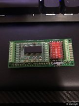
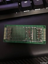
#define NUM_CURRENT_TRANSFORMERS_MONITORED 6
//transformer ratio 1000:1
#define TRANSFORMER_RATIO 1000
//current transformer pins
const int pins[NUM_CURRENT_TRANSFORMERS_MONITORED] = {A0, A1, A2, A3, A4, A5};
//burden resistor value for each current transformer
const float BURDEN_CAL[NUM_CURRENT_TRANSFORMERS_MONITORED] = {135.0, 135.0, 135.0, 135.0, 135.0, 135.0};
//value to multiply P-P value by to get RMS value
const float RMS_MULT = 1.0 / sqrt(2.0);

//current transformer sensor object
class current_transformer {
  public:
    //tried to sort by access frequency
    //sampling start time
    unsigned long start_time = millis();
    //how long to sample each analog input for, in milliseconds
    unsigned long sample_duration = 1000UL;
    //place to put incoming sensor reading
    int sensor_sample = 0;
    //pin which this sensor is associated with   
    byte pin = 0;
    //how many samples have been taken
    int samples = 0;
    //max analogRead() value
    int max_value = 0;
    //result in mV
    float result = 0.0;
    //mA peak-to-peak through resistor
    float curr_resistor_pp = 0.0;
    //mA rms through resistor
    float curr_resistor_rms = 0.0;
    //mA rms through monitored line
    float curr_wire_rms = 0.0;
};//end class current_transformer
//create power_monitor[] objects
current_transformer power_monitor[NUM_CURRENT_TRANSFORMERS_MONITORED];

void setup() {
  //set current transformer sensor pins
  for (int i = 0; i < NUM_CURRENT_TRANSFORMERS_MONITORED; i++)
  {
    //current transformer input pins set to INPUT
    pinMode(pins[i], INPUT);
    //current_transformer class object array power_monitor[]
    //set pin number in corresponding power_monitor[] object
    power_monitor[i].pin = pins[i];
  }
  //serial monitor
  Serial.begin(1000000);
}

void loop() {
  get_current_transformer_reading();
}

void get_current_transformer_reading()
{
  //cycle through sensors, pin numbers can be discontiguous
  for (int i = 0; i < (NUM_CURRENT_TRANSFORMERS_MONITORED); i++)
  {
    //sample for power_monitor[i].sample_duration milliseconds
    if ((millis() - power_monitor[i].start_time) <= power_monitor[i].sample_duration)
    {
      //get a reading from a sensor pin
      power_monitor[i].sensor_sample = analogRead(power_monitor[i].pin);
      //sample rate to help with code efficiency
      power_monitor[i].samples++;
      //if the sensed voltage is greater than the largest voltage seen this sample, set power_monitor[i].max_value
      if (power_monitor[i].sensor_sample > power_monitor[i].max_value)
      {
        //to whatever was sensed
        power_monitor[i].max_value = power_monitor[i].sensor_sample;
      }
    }
    //if the time to sample is over, it's time to calculate some things
    if ((millis() - power_monitor[i].start_time) >= power_monitor[i].sample_duration)
    {
      //try to avoid float division
      //aref / resolution = MAX_VALUE_MULT  5.0 / 1024.0 = 0.00488
#define MAX_VALUE_MULT 0.0048828125
      //power_monitor_results[].result is peak-to-peak voltage from current transformer
      //cast max_value to float
      power_monitor[i].result = float(power_monitor[i].max_value) * MAX_VALUE_MULT;
      //power_monitor_results[].curr_resistor_pp is peak-to-peak current across the burden resistor
      power_monitor[i].curr_resistor_pp = (power_monitor[i].result / BURDEN_CAL[i]) * TRANSFORMER_RATIO;
      //convert peak-to-peak voltages to RMS 1/sqrt(2) approx. .707
      power_monitor[i].curr_resistor_rms = power_monitor[i].curr_resistor_pp * RMS_MULT;
      //derive the current through the ac wire
      power_monitor[i].curr_wire_rms = power_monitor[i].curr_resistor_rms * TRANSFORMER_RATIO;
      //print out the readings
      log_current_transformer_reading(i);
      //reset class variables for relevant pin
      power_monitor[i].max_value = 0;
      power_monitor[i].samples = 0;
      power_monitor[i].start_time = millis();
    }
  }
}

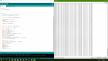
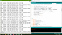
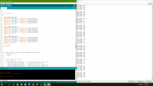
void log_current_transformer_reading(int i)
{
  Serial.print(F("A"));
  Serial.print(i);
  Serial.print(F(" Samples : "));
  Serial.print(power_monitor[i].samples);
  Serial.print(F(" peak-peak : "));
  Serial.print((power_monitor[i].result * 1000.0), 3);
  Serial.print(F("mV c_t_r (peak) : "));
  Serial.print((power_monitor[i].curr_resistor_pp * 1000.0), 3);
  Serial.print(F("mA RMS : "));
  Serial.print((power_monitor[i].curr_resistor_rms * 1000.0), 3);
  Serial.print(F("mA c_t_w : "));
  Serial.print(power_monitor[i].curr_wire_rms, 3);
  Serial.println(F("mA"));
}
 

dstroy

Insanely Active Member
1579703829650.png

making the part of the program that cuts up the string from the cozir environmental sensors more efficient? trying to anyway. knocked of a few thousand micros so far.

I'm moving the cozir sensors in the HPA controller to the spi2uart

library:

ebay link:

Code:
#include <SPI.h>
#include "MULTIUART.h"


MULTIUART multiuart(53);  //CS pin = 53

#define COZIR_STRTOK_CHAR_TO_IGNORE "HTZ \r\n"
#define MULTIUART_SERIAL_ZERO_BUFFER 64

void setup()
{

  //SPI Prescaler Options
  //SPI_CLOCK_DIV4 / SPI_CLOCK_DIV16 / SPI_CLOCK_DIV64
  //SPI_CLOCK_DIV128 / SPI_CLOCK_DIV2 / SPI_CLOCK_DIV8 / SPI_CLOCK_DIV32

  multiuart.initialise(SPI_CLOCK_DIV64);  // set up the SPI and MultiUART Library
  Serial.begin(9600);               // set up Serial library at 9600 bps
  Serial1.begin(9600);

  // Initialise the UART baud rates
  // 0=1200, 1=2400, 2=4800, 3=9600, 4=19200, 5=38400, 6=57600, 7=115200

  multiuart.SetBaud(0, 3);    // UART0 = 9600 Baud
  //  multiuart.SetBaud(1, 3);    // UART1 = 9600 Baud
  //  multiuart.SetBaud(2, 3);    // UART2 = 115200 Baud
  //  multiuart.SetBaud(3, 3);    // UART3 = 115200 Baud
}

void loop()
{
  //serial loopback
  //a typical string from one of my environmental sensors
  Serial1.print("H 00345 T 01195 Z 00651\r\n");

  //  //Send out data on UART
  //  multiuart.TransmitString(0, "UART 0 Test", 12);

  serialOneCozir();

}

void serialOneCozir() {
  //start time is for debug/efficiency monitoring
  unsigned long start_time = micros();
  //reinit costs about 40 micros
  static char ttl_buf[60] = {0};
  static bool newData = false;

  static char LENGTH;
  LENGTH = multiuart.CheckRx(0);  //Check UART 0 for incoming data

  if (LENGTH > 0 && newData == false) {
    multiuart.ReceiveString(ttl_buf, 0, LENGTH); //Collect incoming data from buffer
    //for loop to copy char array should go here if we want to maintain an original of ttl_buf
    newData = true;
  }

  if (newData == true) {
    int index = 0;
    //pieces of data to point to, just humidity temp and co2 for this sensor so 3 pointers
    char *strings[3];
    char *ptr = NULL;
    ptr = strtok(ttl_buf, COZIR_STRTOK_CHAR_TO_IGNORE);
    while (ptr != NULL) {
      strings[index] = ptr;
      index++;
      ptr = strtok(NULL, COZIR_STRTOK_CHAR_TO_IGNORE);
    }
    int temp_hum = atoi(strings[0]);
    float hum = float(temp_hum / 10.0); // divide by 10
    int temp_temp = atoi(strings[1]);
    float temp = float((temp_temp - 1000) / 10.0);
    int co2 = atoi(strings[2]);
    
//    Serial.print("Humidity "); Serial.print(hum);   
//    Serial.print(" temp "); Serial.print(temp);
//    Serial.print(" co2 "); Serial.println(co2);
    unsigned long elapsed_time = micros() - start_time;
    Serial.println(elapsed_time);
    newData = false;
  }
}
 

dstroy

Insanely Active Member
1579798781448.png

550 samples per sec for those current sensors on top of everything else this thing is doing is pretty good!
 

MtRainDog

Blümen Meister
Awesome stuff here! This is pointing me in the right direction for some things I'd like to try. My experience with Arudino is limited to using ultrasonic sensors > arduino > raspberry pi, and opening a simple socket connection to poll for measurements, and record them in sql server express to be displayed in a webpage.

I'd like to go further with that, and raspberry pi's are much more capable nowadays. I'm a .Net developer, and writing .Net Core apps for the RP is right up my alley.

From what I think I'm reading here, you're using the SPI-UART bridge so you can have 4 peripherals? Or better performance than UART? Both?
 

dstroy

Insanely Active Member
Awesome stuff here! This is pointing me in the right direction for some things I'd like to try. My experience with Arudino is limited to using ultrasonic sensors > arduino > raspberry pi, and opening a simple socket connection to poll for measurements, and record them in sql server express to be displayed in a webpage.

I'd like to go further with that, and raspberry pi's are much more capable nowadays. I'm a .Net developer, and writing .Net Core apps for the RP is right up my alley.

From what I think I'm reading here, you're using the SPI-UART bridge so you can have 4 peripherals? Or better performance than UART? Both?
SPI is much faster than uart serial, and the spi2uart has its own buffer so it’s totally asynchronous from the mega, and it doesn’t have clock speed error for baud rates present on the mega at 16mhz so the communication that takes place at 9600 baud is inherently more reliable between the spi2uart and cozir environmental sensors.

I also wanted a loopback uart interface for testing.

Good luck with your projects.
 

MtRainDog

Blümen Meister
Thanks, I am pretty ignorant when it comes to embedded systems. Web servers and databases are my thing, but I've always found this stuff fascinating, and have always wanted to learn more.

Never even considered that you'd need to account for the different clock speeds of the components for the over the wire communications. Makes complete sense though. This really does help!
 

dstroy

Insanely Active Member
I've got 3 INA260 current/voltage/power sensors coming for the 24v,12v,5v busses

I tried to use some ACS712, with a little filter circuit that I made but they suck pretty hard even filtered at detecting small changes. Scrapped that and will just go with something I know will work even though the INA260 is 3x more expensive.
 

dstroy

Insanely Active Member
Differential pressure and electrical conductivity

Ads1115 and sparkfun differential i2c extender

F566068A-96D1-4D8E-A1EF-2F970C54290B.jpeg828CE5D6-A8F2-4F18-9EBE-2FEB2DB50003.jpeg
 

dstroy

Insanely Active Member
I rewrote some of adafruit's ads1115 library to remove delay, added a new function to the library "readADC_connected". New code doesn't sit around for 8ms doing nothing every time it takes a reading.
 

Attachments

MtRainDog

Blümen Meister
I think you can simplify readADC_Connected() with something like

C:
void Adafruit_ADS1015::readADC_Connected() {

    uint8_t channel = m_read_index;

    // If upon entry index is 4 or more, reset to 0
    if (channel > 3)
        channel = 0;

    // if not connected, switch channels until connected
    while (!m_connected[channel]) {
     
        // check bounds
        if (channel == 3) break;
        channel++;
    }

    // increment the index for the next read
    m_read_index = channel + 1;

    // Other work here...

    // Not needed
    //m_switch_channels = true;
}
 
Last edited:

dstroy

Insanely Active Member
I think you can simplify readADC_Connected() with something like

C:
void Adafruit_ADS1015::readADC_Connected() {

    uint8_t channel = m_read_index;

    // If upon entry index is 4 or more, reset to 0
    if (channel > 3)
        channel = 0;

    // if not connected, switch channels until connected
    while (!m_connected[channel]) {
    
        // check bounds
        if (channel == 3) break;
        channel++;
    }

    // increment the index for the next read
    m_read_index = channel + 1;

    // Other work here...

    // Not needed
    //m_switch_channels = true;
}
Thanks for the help!

Lets walk through it, because while what you wrote was less complicated than what I did it wont work.

1. We don't know when this function will be called, or how often.
2. There is an unavoidable 8-9ms conversion delay created by an ADS1115 for each reading it does.
3. If you write the config register on the ADS1115 to set up the mux for single ended read before another read is completed, that will be ignored and previous results will be returned, or erroneous results will be returned

Each time the function is called, without the switch channels flag the channel will switch, which is not desirable.

I can move the onus of control out of the library into my code in the form of timers but then what's the point of having the library.
 
Top