
shimz
vapest
Gonna throw this up here. Mainly for @SoLowDoughLow but inspired by the excellent work of @HydroRed I give you plans to build the doser I've been running on two reservoirs for the last few years.
Please refer to the full instructions.PDF attached.
Here she is, a dually version of my doser. This is two systems in one box: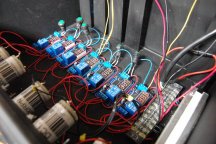
The system automatically fills two reservoirs from my R.O. system plus nutrients from these stock tanks: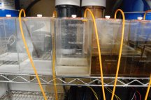
I use Jack's 321 and Potassium silicate/Potassium hydroxide for pH up.
Here is the basic building block of this system, a simple Chinese relay timer board that has proven to be very reliable (except for that time I got one wet...):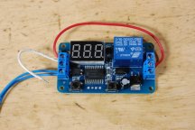
Here are the four boards in series. The first board is triggered by a float switch, which turns on an electric water valve for the amount of time programmed, at the end of the time the second board is triggered, which turns on a peristaltic pump for its programmed time, then the next and so on. You could hook up as many or as few boards as you need: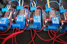
The red wires are +12VDC and the blue are grounds. I used a little waterproof LED power supply but you could use almost any 12V supply over 1A output.
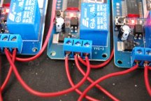
Power enters the first board (the one on the right with the yellow wires) at the COM terminal. That's the one on the bottom middle. Another wire shares that connection and runs up to the VCC terminal providing power to the first board. The yellow wires go through the float switch and back. One yellow wire shares the VCC terminal with the red wire and the other is connected to the IN terminal. When power is let through by the float valve, the board is triggered and the cycle begins.
Here are some closeups of the connections: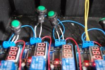
This is a closeup of the terminal strip. This just makes it easier to distribute the grounds and connect the driver to the power cord and driver to board power wires: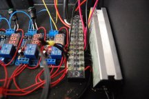
I used the large sockit box. It's big enough to hold two full fill systems. I spec'd the medium box in the materials list, but you could actually get a system to fit in a small sockit box: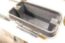
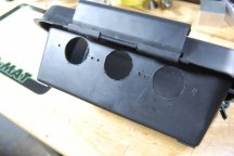
Of course, feel free to use any box you may have laying around or no box at all!
I hope some of you attempt this. Please read the full instructions in the attached PDF. I'm here to help if you need it, so post away!
Please refer to the full instructions.PDF attached.
Here she is, a dually version of my doser. This is two systems in one box:
The system automatically fills two reservoirs from my R.O. system plus nutrients from these stock tanks:
I use Jack's 321 and Potassium silicate/Potassium hydroxide for pH up.
Here is the basic building block of this system, a simple Chinese relay timer board that has proven to be very reliable (except for that time I got one wet...):
Here are the four boards in series. The first board is triggered by a float switch, which turns on an electric water valve for the amount of time programmed, at the end of the time the second board is triggered, which turns on a peristaltic pump for its programmed time, then the next and so on. You could hook up as many or as few boards as you need:
The red wires are +12VDC and the blue are grounds. I used a little waterproof LED power supply but you could use almost any 12V supply over 1A output.
Power enters the first board (the one on the right with the yellow wires) at the COM terminal. That's the one on the bottom middle. Another wire shares that connection and runs up to the VCC terminal providing power to the first board. The yellow wires go through the float switch and back. One yellow wire shares the VCC terminal with the red wire and the other is connected to the IN terminal. When power is let through by the float valve, the board is triggered and the cycle begins.
Here are some closeups of the connections:
This is a closeup of the terminal strip. This just makes it easier to distribute the grounds and connect the driver to the power cord and driver to board power wires:
I used the large sockit box. It's big enough to hold two full fill systems. I spec'd the medium box in the materials list, but you could actually get a system to fit in a small sockit box:
Of course, feel free to use any box you may have laying around or no box at all!
I hope some of you attempt this. Please read the full instructions in the attached PDF. I'm here to help if you need it, so post away!
Attachments
-
252.9 KB Views: 139
Last edited:
