Hydro
PICK YOUR OWN
The finished product measures 20" x 20" and draws approximately 200W of dimmable LED light.
**DISCLAIMER** It is not a difficult build, but will require some basic mechanical and electrical abilities.
If you are not good at wiring or arent mechanically inclined, you may want to consider a premade light fixture.
PARTS LIST:
(4) Citizen CLU048 1212's (36V)
(4) 120mm Passive Pin Heatsinks
(1) Mean Well HLG 185H-C1400B Driver (dimmable)
(4) BJB COB Holders
(1) tube Arctic Silver Thermal Paste
(12) ft. 1" Aluminum Angle
(8) 1/2" nuts & bolts
(28) 1/4" M3 screws (usually standard size used for predrilled/tapped heatsinks)
(8') 18 gauge wire (solid & rated for 300V+)
(2) Waterproof Junction Boxes
(1) 100K Potentiometer
(1) 6' Power Cord with plug (3 wire grounded)
(4) Eye Bolts & nuts
(4') Small Chain
(2) wire nuts
THE BUILD:
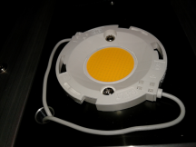
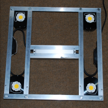
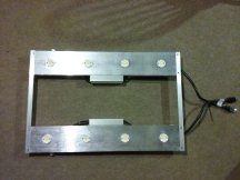
Cut 4 pieces of the aluminum angle @ 20". Drill holes for the 1/2" bolts (as indicated by the red dots) to make a square frame as seen in the picture. Be sure to use the HeatSinks to give the proper space so they fit once assembled. You can now apply the thermal paste, then install the COBs and the BJB holders to the heatsinks with the M3 screws.
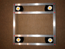
Line up the heatsinks & drill holes in the frame so you can mount the pre-drilled and tapped heatsinks to the frame with the M3 screws (indicated by the purple dots in the pic).
Be sure to leave the hole in the heatsinks available and accessible because this is the hole you will use to run the wires from the COBs back up through to the next COB and then to the driver so everything stays neat and tidy. I placed my heatsinks so that the hole is facing the corners of the aluminum frame.
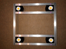
Once the frame and heatsinks are assembled, now cut (2) pieces of aluminum angle at 12" each. These are going to be the "holder" for the driver and will be how you attach the driver to the frame. It will also add to the rigidity of the frame overall. You will need to notch out some of the edges of the aluminum angle to get it to fit how I have mine, but this will allow the driver supports to fit flush with the rest of the frame.
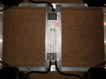
Drill holes to affix the (2) 12" center rails as pictured. Drill holes to affix the driver to the now mounted rails using the M3 screws.
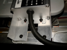
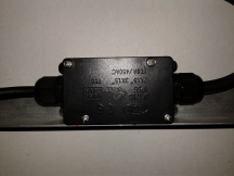
Drill and affix the (2) junction boxes on opposite sides of the frame (at each wired end of the driver) and wire the A/C side of the driver and the 6' power cord in one junction box
(as pictured).
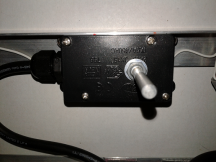
As for the other junction box, you will drill a hole in the top of the junction box to install the potentiometer and wire it to the dimming wires from the driver (as pictured).
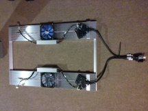
Run your wires from COB to COB in series & be sure to run the wires thru the holes in the HeatSinks then connect the pos & neg to the DC side of the driver.
Your light should be taking full shape by now and the wires should look something about like this:
You can now drill holes to attach the eye bolts on the 4 points as seen in the picture.
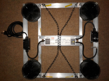
Attach the chain to the eye bolts. I used approx 24" of small black unwelded chain on each side.
I also used Kapton tape to keep the wires affixed to the inside edges of the aluminum angle which keeps everything tidy and free from being able to get snagged etc.
Your light is now finished and ready to grow some plants.
If you have questions, feel free to ask and I'll try to help to the best I can. Happy growing!!
**DISCLAIMER** It is not a difficult build, but will require some basic mechanical and electrical abilities.
If you are not good at wiring or arent mechanically inclined, you may want to consider a premade light fixture.
PARTS LIST:
(4) Citizen CLU048 1212's (36V)
(4) 120mm Passive Pin Heatsinks
(1) Mean Well HLG 185H-C1400B Driver (dimmable)
(4) BJB COB Holders
(1) tube Arctic Silver Thermal Paste
(12) ft. 1" Aluminum Angle
(8) 1/2" nuts & bolts
(28) 1/4" M3 screws (usually standard size used for predrilled/tapped heatsinks)
(8') 18 gauge wire (solid & rated for 300V+)
(2) Waterproof Junction Boxes
(1) 100K Potentiometer
(1) 6' Power Cord with plug (3 wire grounded)
(4) Eye Bolts & nuts
(4') Small Chain
(2) wire nuts
THE BUILD:
Cut 4 pieces of the aluminum angle @ 20". Drill holes for the 1/2" bolts (as indicated by the red dots) to make a square frame as seen in the picture. Be sure to use the HeatSinks to give the proper space so they fit once assembled. You can now apply the thermal paste, then install the COBs and the BJB holders to the heatsinks with the M3 screws.
Line up the heatsinks & drill holes in the frame so you can mount the pre-drilled and tapped heatsinks to the frame with the M3 screws (indicated by the purple dots in the pic).
Be sure to leave the hole in the heatsinks available and accessible because this is the hole you will use to run the wires from the COBs back up through to the next COB and then to the driver so everything stays neat and tidy. I placed my heatsinks so that the hole is facing the corners of the aluminum frame.
Once the frame and heatsinks are assembled, now cut (2) pieces of aluminum angle at 12" each. These are going to be the "holder" for the driver and will be how you attach the driver to the frame. It will also add to the rigidity of the frame overall. You will need to notch out some of the edges of the aluminum angle to get it to fit how I have mine, but this will allow the driver supports to fit flush with the rest of the frame.
Drill holes to affix the (2) 12" center rails as pictured. Drill holes to affix the driver to the now mounted rails using the M3 screws.
Drill and affix the (2) junction boxes on opposite sides of the frame (at each wired end of the driver) and wire the A/C side of the driver and the 6' power cord in one junction box
(as pictured).
As for the other junction box, you will drill a hole in the top of the junction box to install the potentiometer and wire it to the dimming wires from the driver (as pictured).
Run your wires from COB to COB in series & be sure to run the wires thru the holes in the HeatSinks then connect the pos & neg to the DC side of the driver.
Your light should be taking full shape by now and the wires should look something about like this:
You can now drill holes to attach the eye bolts on the 4 points as seen in the picture.
Attach the chain to the eye bolts. I used approx 24" of small black unwelded chain on each side.
I also used Kapton tape to keep the wires affixed to the inside edges of the aluminum angle which keeps everything tidy and free from being able to get snagged etc.
Your light is now finished and ready to grow some plants.
If you have questions, feel free to ask and I'll try to help to the best I can. Happy growing!!

")